With the rise of the Internet and e-commerce, computer communication has become one of the hottest fields in Computer Engineering. Your Coldfire demonstration board actually has a NE2000 compatible Ethernet card built into it. With this lab, you’ll learn about how the IEEE standard for Ethernet works and how it relates to the Coldfire board.
Ethernet Specification 802.3, Type 10-Base-T
The NE2000 compatible chipset on the Coldfire Microprocessor incorporates the IEEE 802.3 Ethernet Standard for communication. Although the protocol is already implemented on the board, it is important to understand how it works.
The Ethernet Specification covers the Physical and Data Link Control layers of the OSI network model as well as the MAC and Physical Layers of the IEEE 802.3 standard for CSMA/CD bus networks. CSMA/CD stands for "Carrier Sense Multiple Allocation with Collision Detect".
Theory of Operation
A central controller or server does not manage the communication channels of CSMA/CD networks. There are also no pre-allocations of frequency bands or timeslots for users. Essentially, if there is now carrier sensed on the media (ie. Nobody is transmitting) a user may contend for the channel. In the event two users contend for the channel at the same time there will be a collision. The collision will be detected and each user will be given a pseudo-random retransmission delay computed using a truncated binary back-off algorithm.
So at any point a user may do one of the following:
10 BASE T
The type of network supported by the Coldfire is a 10-Base-T network.
The "10" represents the fact that data are transmitted over the network cable at a rate of 10 Mbits. The "Base" represents the fact that data are being transmitted in baseband transmission. The "T" represents that the cable used is "Twisted Pair". Twisted pair wire is consists of eight wires. Each pair (four pairs total) are twisted in a double helix fashion to cut down on field effects (noise) produced by the carrying of current. The maximum interstation distance allowed in a 10 base T network is 70 meters, and the cable length between stations must be at least 1.5 - 2 meters. In a 10 BASE T network the nodes (computers, printers, etc) are arranged in a "Star" format in which each node of a subnetwork is connected to a hub.
Physical Layer
The physical layer of the network is responsible for Data Encoding and Channel Access. Data Encoding involves the removal of the Preamble Bytes for Synchronization, bit encoding, and bit decoding. Channel Access controls the transmission and reception of the encoded data bits, as well as the carrier sensing and collision detection.
Data Link Layer
The Data Link Control layer is responsible for Data Encapsulation and Link Management. Data Encapsulation controls the framing and handling of the source and destination addresses, as well as the error detection of the physical channel. The Link Management controls the channel allocation (to avoid collisions) and the collision contention resolution.
Channel Encoding
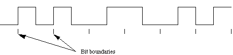
Each bit is Manchester Encoded. Manchester coding provides for a 50 percent duty cycle and ensures a transition in the middle of every bit cell.
If you want Logic 0 the bit is encoded with a 1 to 0 (downward transition at bit
center)
If you want Logic 1 the bit is encoded with a 0 to 1 (upward transition at bit center)
The following diagram shows a typical Manchester encoded signal with the corresponding binary representation of the data (0,0,1,0,1,1) being sent.
Packet Format: (IMPORTANT!!!)
| SECTION Preamble |
# OF BYTES 7 Bytes |
DESCRIPTION Alternating ones and zeros |
| Start Frame Delimiter | 1 Byte | Like Preamble but ending in two ones. 10101011 |
| Destination Address | 6 Bytes | Specifies to which station the packet is being addressed. If first byte is '1' the packet is "multiaddressed" to a logical group. |
| Source Address | 6 Bytes | Specifies which station is sending the packet. |
| Length | 2 Bytes | Number of Bytes of Data Sent |
| Data | 46 - 1500 Bytes | 48 Bytes recommended to distinguish from collision fragments. If data is less than 46 bytes, bytes are appended at the end to total 46. |
| Frame Check Sequence | 4 Bytes | 32 bit CRC. CRC computed on Destination Address, Source Address, Length, and Data. |
Error Correcting Code
Ether is actually a concept from modern physics used at one time to explain how waves traveled through a vacuum. Before the idea of a electromagnetic wave was imagined, the ether was believed to be a hypothetical non-material, imponderable medium supposed to permeate the whole of space and to transmit the waves of light, radiant heat, and electromagnetic radiation. Ethernet, therefore, is a communications protocol that can work in any medium: radio, wire, light, and other forms of communication.