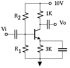
Figure 1 Common emitter amplifier
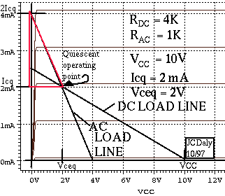
The DC load line is drawn on the transistor characteristics. It represents the voltage current relationship for the collector circuit. For the DC loadline, open circuit the emitter capacitor and write a loop equation around the collector circuit.
Vcc = Vce + Rdc*Icwhere Rdc = Rc + Re (4K in this example). The DC load line is a plot of Ic vs Vce using this equation.
|
Figure 1 Common emitter amplifier |
|
AC Load Line
The AC load line is a plot of the current through the transistor vs the voltage across it for AC signals. For AC analysis assume capacitors and power supplies (Vcc) are short circuits. Rac=Rc=1K is the resistance around the collector circuit with capacitors shorted. Writing the loop equation around the collector circuit.
vce = -Rac*icwhere vce and ic are the AC collector to emitter voltage and the AC collector current. The AC load line must pass through the quiescent operating point. When the AC signals are zero, Ic = Icq and VCE = Vceq. When currents and voltages vary, the operating point moves along the AC loadline.
The circuit shown in figure 1 has been designed for maximum voltage swing by placing the operating point in the middle of the AC load line.
A simple equation assures maximum swing.
This equation is used to select resistors for maximum AC collector voltage swing.Icq = Vcc/(Rac + Rdc)
Consider the red triangle drawn with the AC load line as hypotenuse. The horizontal side is Vceq. Since the operating point is in the center of the AC load line, the vertical side of the triangle is Icq.
Vceq = Icq*Racwhere 1/Rac is the slope of the AC load line. Plug this equation into the equation for the DC loadline,
Vcc - Rac *Icq = Rdc*IcqIf there are no capacitors Rac = Rdc and Icq = Vcc/2Rdc.Icq = Vcc/(Rac+Rdc)