ICED FPGA Interface
University of Rhode Island - ELE Dept.

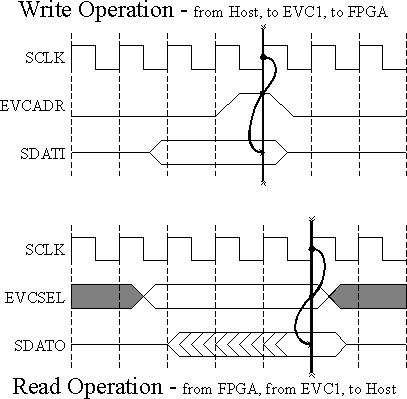
Timing
As I've said a million times, in digital systems timing is everything.
In particular, I'm now going to describe and show what happens when
there are 1) writes to, and 2) reads from
the slave interface using a C program running on the Host ("host
program", such as icmon). Recall that the "Host" is
just the Sun workstation that physically contains the VCC EVC1 FPGA
card.
-
Writes: a write to the EVC1 is initiated in
our host programs by assigning a value to an element of the "evc"
array, viz.:
evc[0] = 529;
In the above example, the number "529" is written to the EVC1. The
physical details:
-
529 is NOT stored in the slave interface of the EVC1, it is sent directly
from the SBUS to the 32-bit SDATI bus.
-
The SCLK is always ticking away, at a clock frequency of 25 MHz.
-
The array index being "0", the EVCADR(0) line is asserted after the data
has been stored in the EVC1 register.
-
The SDATI lines are guaranteed to hold the valid data (529) when EVCADR(0)
is asserted (it's active high, so that's when it's a '1').
-
THEREFORE: you can use the coincidence of the EVCADR(0) line and the rising
edge of SCLK to latch the data into one of YOUR registers.
-
NOTE: the EVCADR(0) line will ONLY be asserted when evc[0]
is written to.
-
See the timing chart below for clarification.
-
Other writes: evc[1] through evc[7] are
defined and correspond one-to-one with EVCADR(1) through EVCADR(7). They
work the same way as evc[0] and EVCADR(0). All of these
array elements are assumed to be 32-bit (4-byte) words.
-
Reads: a read from the EVC1 is initiated in
our host programs by assigning the value of an evc array element
to wherever we want the data, say "temp":
temp = evc[8];
The data that gets read is whatever happens to be on the 32-bit SDATO
bus in your hardware design when the C assignment is executed. Details:
-
The SDATO data gets latched into a register in the slave interface part
of the EVC1 to synchronize it with the SBUS.
-
Somewhat before the data is latched, the three EVCSEL lines take on the
value of the evc array index mod 8; e.g., in the example
above, evc[8] being read causes EVCSEL to be set to the
3-bit value: "000".
-
You can only read from 8 "locations", corresponding to evc[8]
through evc[15].
-
The EVC1 designers' intent was that your design would connect all possible
outputs to SDATO through a multiplexer, and the multiplexer's select lines
would be driven by the EVCSEL lines. Other approaches are possible.
September 19, 2000 | Gus
Uht | uht@ele.uri.edu