This tutorial will walk you though setting up a simple combinational logic system made of two gates, an AND gate and an XOR gate. The inputs will be driven from switches that you can flip around while the simulation is running, and the outputs will be visible with a Scope block (which simulates an oscilloscope display). I'm assuming that you've extracted the library and added it to the Matlab path; if not, go here first.
You might want to print this page out to make it easier to refer to while you follow along; if you are on a machine with dual monitors like the ELE lab machines you can also move this window onto the smaller screen and leave the bigger one free for running Simulink. Simulink tends to be a space hog in terms of screen real estate; you end up opening many windows while working, so dual headed systems are a welcome improvement.
Start up Matlab and click on the Simulink icon (see the red box in the screenshot below), or type 'simulink' in the command window: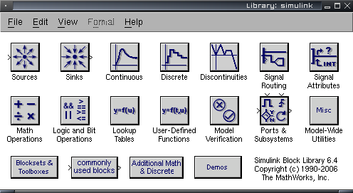
Now you are ready to start placing blocks into the model. You do this in Simulink by dragging and dropping the block you want from the library window into your model.
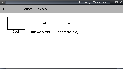
Drag and drop a 'False' block from the library window you opened earlier into your model. Also drag and drop a 'True' block to your model; these two blocks provide constant outputs of 0 and 1, respectively. Go to File, Open, and open the InputDevs/Switches library. Drag and drop two 'Manual Switch' blocks into your model.
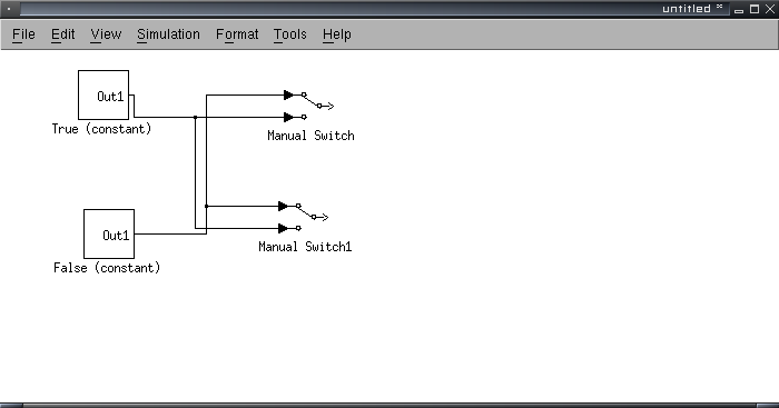
Now we can start connecting things. Click and drag between the arrows on the blocks to connect them with wires. You need to connect the top input of both switches to the False block, and the bottom input of both switches to the True block. It's usually easier to work the connections from the input port of the destination block back to the source block or wire, instead of the other way around.
Tips:
So far your model should look like this:
Now we need something to connect the switches to. Go to File, Open (on any library window you have handy; the File menus on all the windows are equivalent), open the Logic directory, and open the 'LogicGates' library. You should get another library window like this:
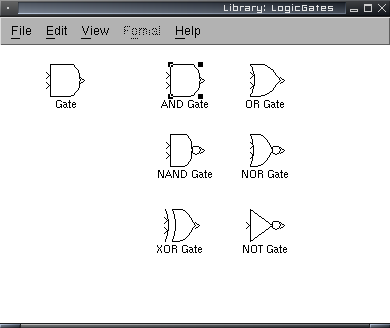
Place an AND gate and an XOR gate into your model. Then connect the top input of both gates to the top switch, and the bottom inputs to the bottom switch.
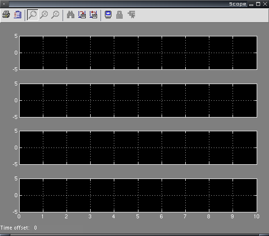
Go back to the main Simulink block library and double-click on the 'Sinks' block library. Drag and drop a 'Scope' into the model; you can close the Sinks after you've got the Scope. In your model, double-click on the Scope block to bring it up. Click the second icon at the top left of the Scope window (the tooltip is 'Parameters'); in the dialog that pops up set the number of axes to 4 instead of 1 and click OK. The scope window should now look like this:
Connect the outputs of the two switches to the top two inputs of the Scope block, and the outputs of the two gates to the bottom two inputs of the Scope. The traces on the Scope display are in the same order as the connections are.
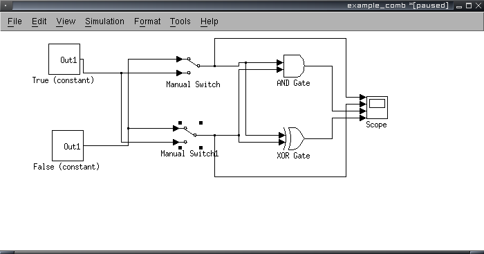
The end result should look like this:
Now go to the Simulation menu and click on 'Configuration Parameters'. Set the Solver options the way I have them in the next screenshot:
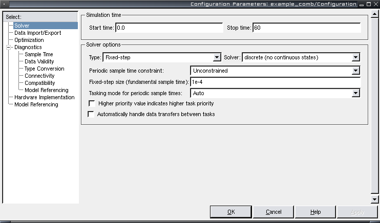
The changes are Type to 'Fixed-step', Solver to 'discrete', Fixed-step size to 1e-4, and Stop time to 60.
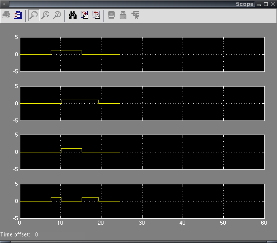
Now you can let it rip! Click Simulation, Start. If all goes well, four traces should start drawing in the Scope window. You can double-click on the switches in the model to change them while the simulation is running and watch the Scope to see what happens.
Example screenshot (your traces will vary; look at the upper two traces to see what I did with the switches):
This simulation runs for 60 units of time (or until you stop it). The magic 1e-4 sample step makes a unit of time approximately 1 second of real time on a modern machine. There seems to be no way to get Simulink to run truly real-time.
To go beyond this simple tutorial, you just need to experiment. Start opening up the other libraries, both in Simulink itself and from the downloaded file, and try out the various blocks. You'll find you can double click on many blocks to open another window showing what's inside the block. I've tried to implement the library blocks in the ways that they might be designed in ELE201 lectures, to help you understand how they work.
When the ELE201 lectures get into sequential logic and flip-flops, the second tutorial on sequential logic will be helpful to you.
The picture on the main page of this site is a screenshot of the guts of the 256x8 RAM chip in the Logic/Mem library; for an example of what something really big made in Simulink looks like, check it out. Double click on the blocks in the big RAM to open more blocks up, from which you can open more blocks... there's a whole hierarchy of blocks involved. This block is difficult to actually use due to the bus objects that need to be loaded, so it is interesting mostly for examples. If you're interested in actually using it, let me (simoneau at ele dot uri dot edu; address not spelled out to avoid spammers) know and I'll show you how.
You can download the completed example here.